|
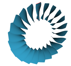
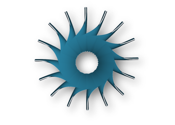
To carry on with the demonstration of GBS applied to turbomachinery, we are pleased to present the CAD issued of a design process based on thermodynamics specifications and design rules. The impeller is now ready for 3d CFD computation or integration inside the final product! GBS: https://github.com/ssg-aero/gbs #turbomachinery #compressor #blade #stage #opensource #design #software #CAD #engineering #engineer #geometry #mechanical 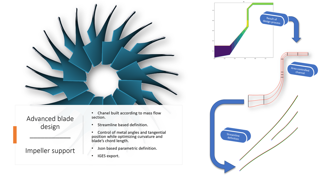
0 Commentaires
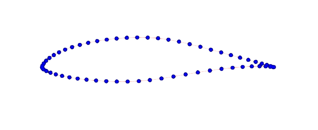
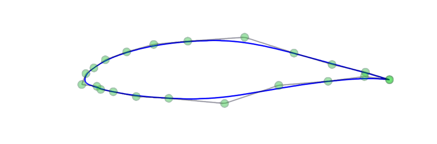
We are pleased to announce the release of our open source library geometrical GBS. ssg-aero/gbs: gbs is a c++ header library to build and manage NURBS, some optional module are used for visualization and export. This library is compatible with OpenCASACADE and has a python biding. (github.com) In a nutshell GBS is a powerful C++ header library to manage BSpline geometries. For now its capabilities range from basic geometry creation in a rational o irrational fashion:  To more advanced geometrical creation algorithms: Points approximation:
Surface creations from profiles:
More technical show case coming.
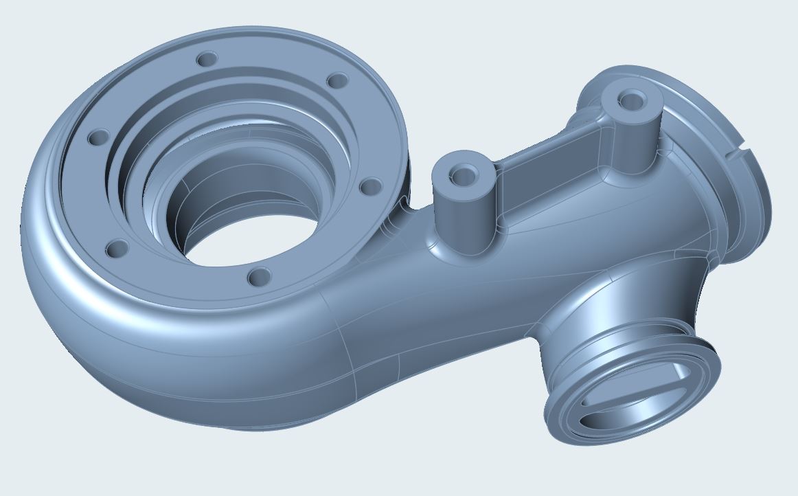
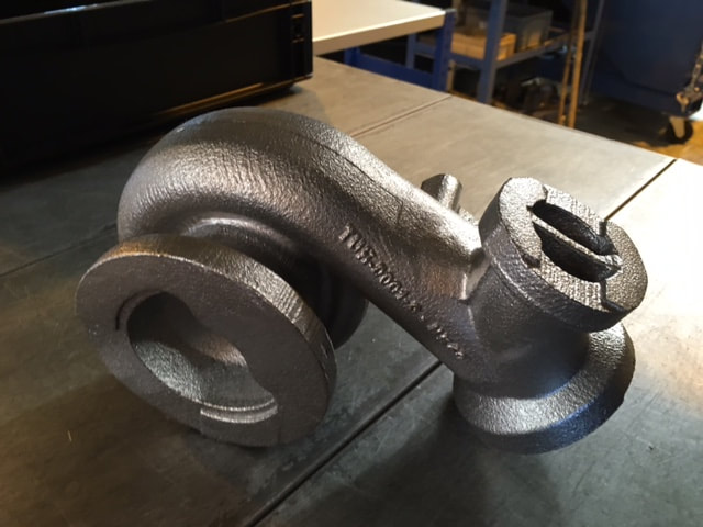
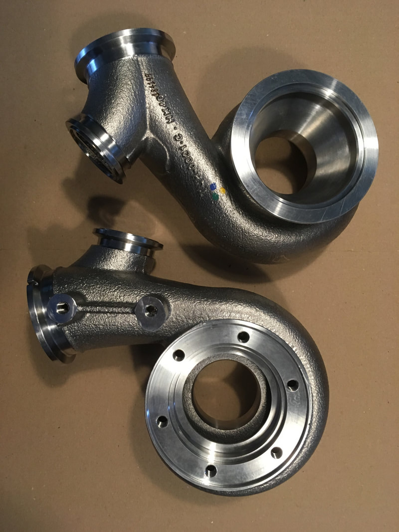
We are very proud to announce the delivery of the 2 very first SSG-AERO physical parts to IFP Energies nouvelles (IFPEN). With the support of our long partner BV-Proto, we designed the geometry to match the geometric requirements of IFPEN, and found competent efficient suppliers to cast and machine them. We are so proud of these 2 turbines volutes we thought it would be nice to share some pictures : We are eager to see them mounted and tested, and wish IFPEN the best for their projects !
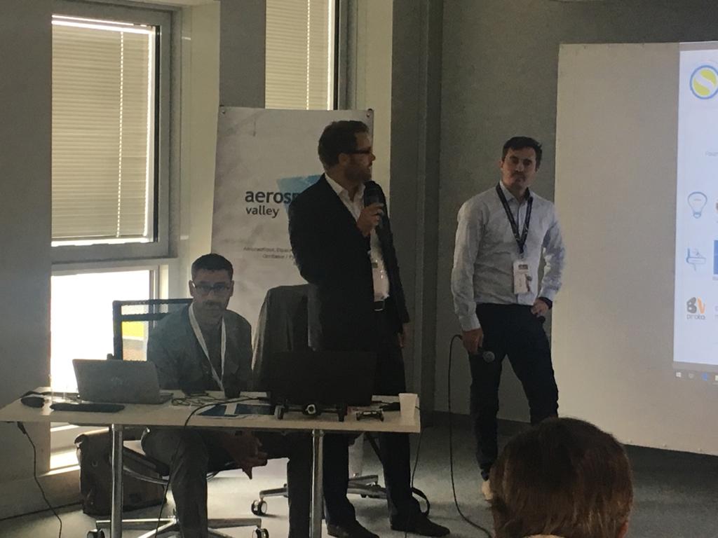
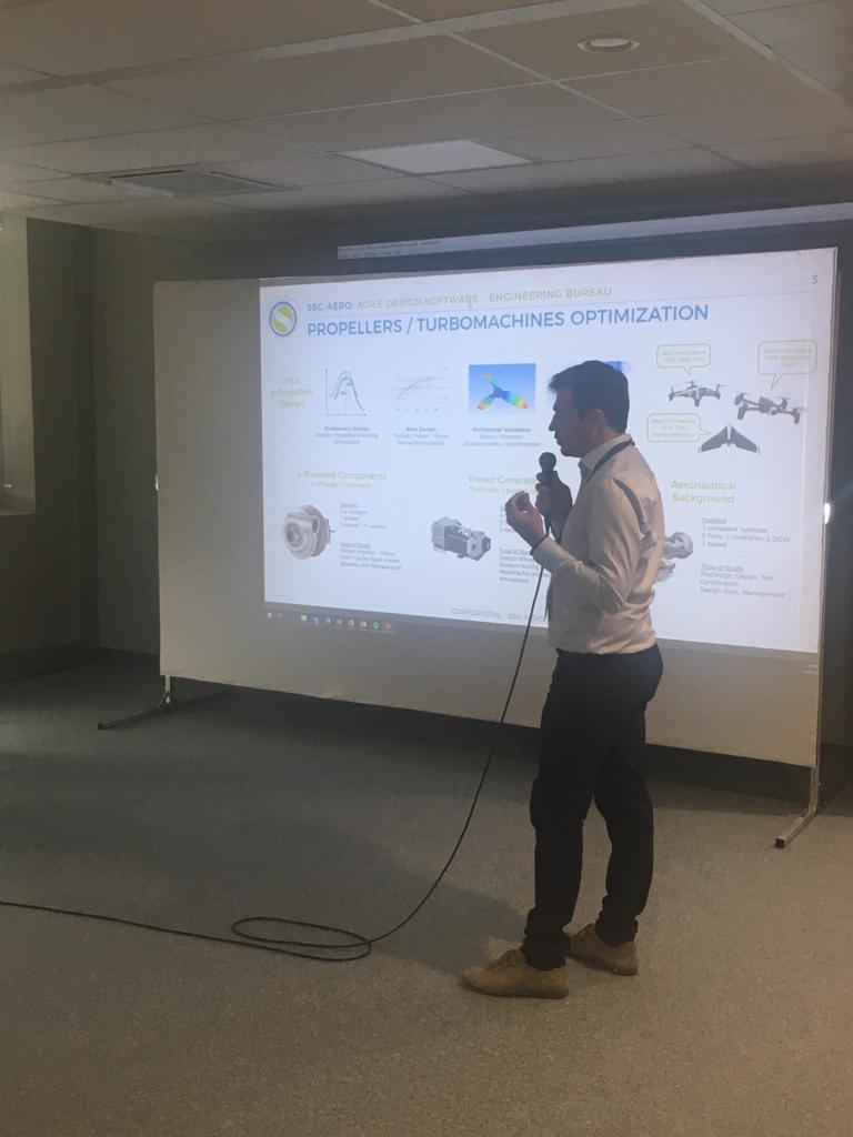
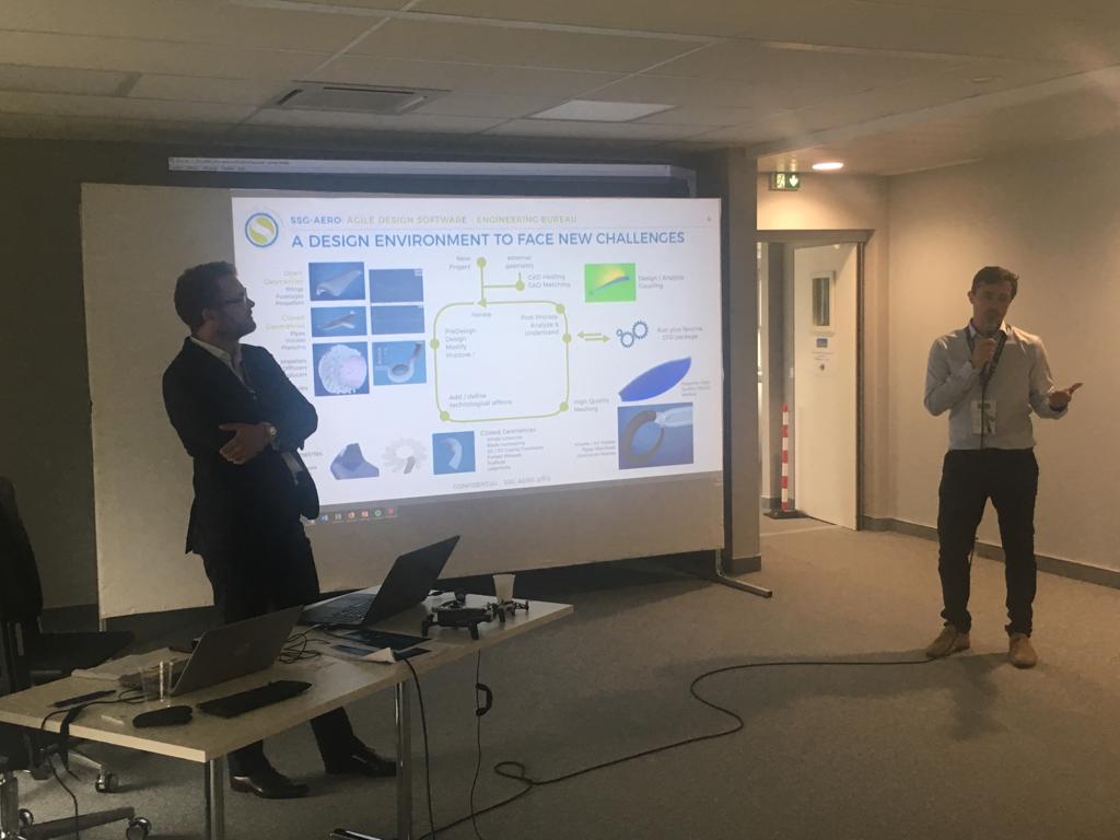
Keywords: Aerospace Valley, electric aircraft, hybrid propulsion, urban mobility French Aero titans and Start-ups together to discuss a major trendSSG-AERO was present during the seminar organized by AeroSpace Valley, one of the French Aero Clusters. During one complete day, a complete overview of all the current developments aimed at reducing the aero carbon footprint and to change local mobility were presented and discussed. Airbus, Safran, Thales and Liebherr Aerospace shared their accomplishments and how they prepared and envisioned this major change in the Aero transportation world. Presentations also focused on the numerous hurdles on the way towards the electrification and hybridization of flying machines allowing free discussions with small companies. Some nice concepts...Time was also given to prospection and science-fiction, with some very interesting concepts : ... and a chance to introduce SSG-AERO!We are very grateful to the Aerospace Valley team, which allowed us to be in the pool of small companies with a 20min slot to present our services ! We introduced SSG-AERO, focusing especially on
For those interested, our presentation is available for download by clicking on the icon under these words...
SSG-AERO is proud the be a member of Aerospace Valley, one of the french cluster focusing on aeronautics. Keywords: release, geometry, volute, software, demonstration, CAD Introducing our very first demonstratorQuoting famous French singer Alain Bashung, the fight to design proper volutes is now gone into smoke and ashes: SSG-Aero is very proud to introduce the first demonstrator of its line of products: the Volute Designer. 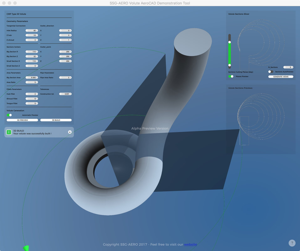 Simple in appearance, it includes all the power of our algorithms in one demonstrator, enabling users to test on template and play around the parameters. DownloadFor those interested, here is a link to the download form, where the only price you’ll have to pay is provide limited information about you so we can keep you updated on our developments in a more personal way: InstallationOur Demo Software is only available for Windows, for timing purposes only. Our software shall be available on all the platforms. To run our demo software,
Mini TutorialThe following videos shows how it works and what it does: The concept of the mini interface is fairly simple: 1 window for control, 2 for analysis, and the geometry in the background:
As we deal with compressor volutes here, the smallest section has to be positioned inside the biggest section. The fillets radius value on the sections can equal zero, hence allowing a slope discontinuity in the sections. If ever a problem occurs during the construction of the surface, a message will pop-up, and you will see how far the geometry was build in the background. Most of the time, the limits are reached when the tongue shape requires a complex fillet shape, such as an evolutive fillet radius, or when the tangential connection does not properly intersect the volute itself. There are some other limitations. The most notable is the value of the fillets. If the user asks for a big fillet radius on a very small section, there may not be a solution. On the other extreme, very small fillets can be hard to be visualized. If ever you are used to extremely small volutes, change scales! On the export sections, we’ll manage everything so that your geometry is great... whatever its size! Of course the product can export the geometry into an IGES file… but we keep this functionality for customers. Thanks for your understanding! Future DevelopmentsThe template used to generate the volute in our demonstrator is quite simple, but shows the potential of our tool. Using the same ergonomics and algorithms, we are now working hardto implement more shapes into it: The CMP TYPE01 is under tests and almost ready for integration! These templates will cover most of the basic industrial cases. Of course we are also available to develop your own templates for a personal version of the volute designer ! We are also planning to create a constraint-based shape optimizer to free designers totally from templates. A bigger Picture As mentioned in earlier posts, this demo is a glimpse of a bigger project where SSG-AERO shall put all its experience to help people master their designs, not the tools they work on. Our design environment shall enable to construction of complete turbo-machines. We did not forget the volute multi-grid structured mesh, which is currently being migrated from our old GUI… ConclusionPlease feel free to test and feedback us on this glimpse of our work.
We do thank you for your attention, and shall keep you posted here ! SSG-AERO Keywords: structured mesh, hexahydron, CFD, pipes, volutes, fast convergence, numerical dissipation IntroductionIt is common to hear engineers pretend they do not bother with meshing, and used this or that automatic mesh filling software in order to quickly simulate the latest evolution of their design. It is true that meshing is a quite complex science (may we call it craftsmanship) where numerous types of skills are involved. Yet in the end the quality of the mesh is one of the key parameters in the quality of the solutions your favorite Computational Fluid Dynamics (CFD) package shall provide… Among the meshing techniques, one is famous for all its qualities, and all the difficulties to play with it: the structured multi-blocks meshes. This article focuses on their key advantages, how structured multi-blocks meshes can provide lightning fast high quality simulation results, and how some new tools in development at SSG-AERO will soon allow many designers to rethink their use of the meshing tools on the market. What is a structured meshMost of the tools providing simulation packages to predict flow behavior are based on a mesh that fills the volumes on which the computations have to be run. What happens is that the fluid dynamics equations called Navier-Stokes Equations are so complex they require to discretize the volumes into very small elements where differences can be estimated, and feed the solvers to reach the solutions for a given set of external / boundary conditions. There are numerous techniques used to fill these volumes, and they use in most cases the following elementary volumes to do so: 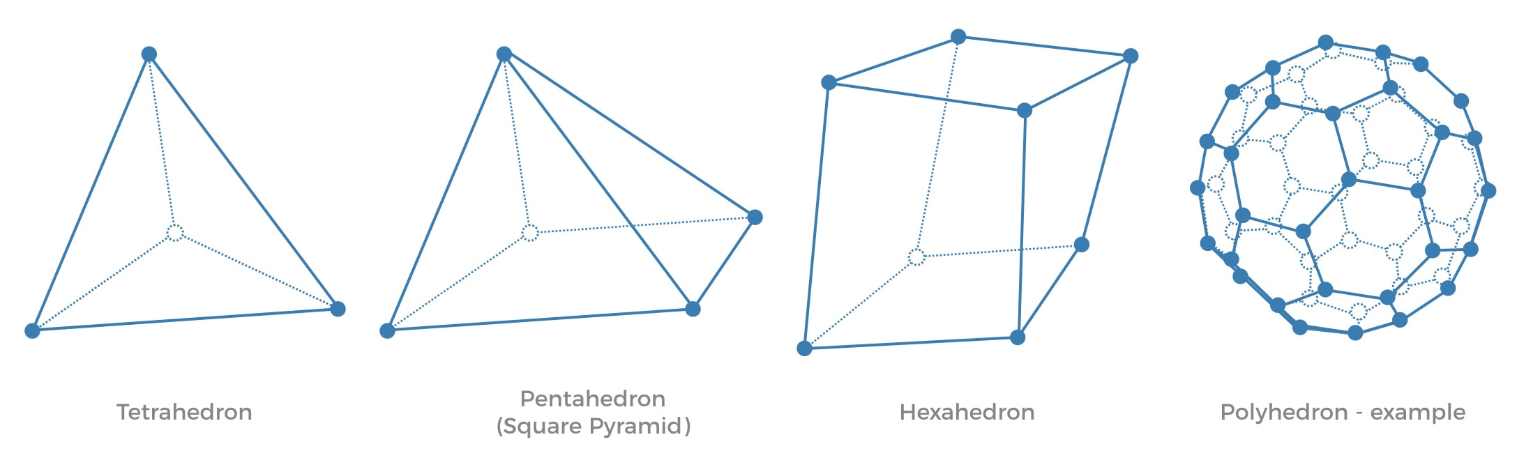 These elements can be used at the same time or not, and meshes are thus classified in two categories:
All the meshes discretize the same domain with two walls where the cells sizes have to be small in order to properly take into account the strong variations of speed from zero at the wall to any potential value farther from it - this refinement is called meshing the boundary layer. 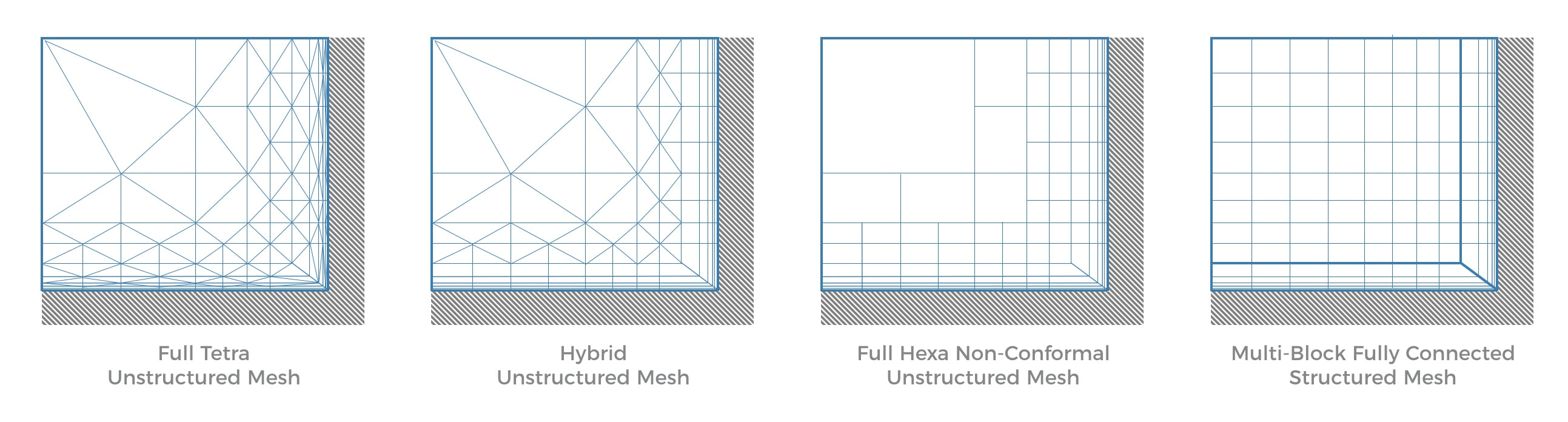 What makes structured meshes better It is always good to keep in mind the purpose of a mesh in CFD, which is to discretize a complex volume into small parts on which a flow simulation shall be run. This means that a very complex and heavy algorithm will use this discretization and travel through it hundreds of times to evaluate differences and solve Navier-Stokes equations using numerical schemes. As for the meshes, the most common CFD solvers using meshes are organized in 2 families:
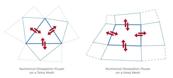
Most of these solvers use the same type of resolution schemes and stabilization schemes which means that for a given type of flow (subsonic, supersonic, incompressible, …), the two solvers are comparable apart from how they manage the grid. Thinking about what makes a good mesh a really good mesh requires to understand the challenges put together in a CFD simulation. A good simulation needs to :
Looking at the mesh through this prism, the advantages of the structured meshes are straightforward :
 Put all together, it means that using a structured mesh on a unstructured solver can be very efficient. SSG-AERO has experienced a factor 2 to 5 acceleration factor between an unstructured mesh and a structured mesh on the exact same configuration. This has been confirmed on other solvers, see https://www.linkedin.com/pulse/why-structured-cfd-grids-still-style-rachael-hopwood-jarvis for instance. On top of this, using structured meshes allows the use of structured solvers, which are intrinsically faster as they use the power of the structured mesh to quickly reach information. As the mesh are organized as big 3D tables, all the data can be organized so and going though these elements and computing differences is as fast as reaching the next or previous element in a table, something powerful programs in fortran or C++ do in no time. To perform the same operation, unstructured meshed use what is called a connectivity table to move from one element to its neighbors, losing time in the process and using additional memory. 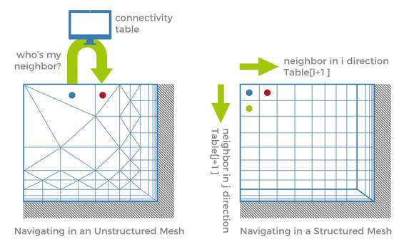 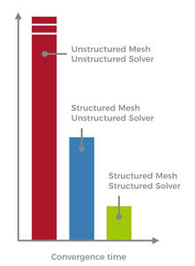 The usual speed up factor between structured and unstructured solvers is around 3. Structured meshes are hence the best discretization technique to run a CFD simulation, as long as precision and prediction are involved. Aerospace and aeronautic companies make no mystery that most of their aero and hydro simulations are run using this type of meshes as their reference : quote from http://blog.gridpro.com/grid-generation-an-art-or-science/ "Long term CFD engineers in certain specialized fields like hypersonic assure structured multi-block is the only way for them to get accurate reliable numbers." So why don't engineers use them more often ? The time usually required to generate a structured mesh stops most users from investing in such a performant technology, pumping most of the engineering time faster than a black hole. One has to think about:
In the meantime unstructured meshes can automatically fill any type of volume, meaning that the design process can be very fast, at the potential cost of precision, CPU time and memory needs. Structured meshes at the service of your design So if you are not a big moustache experienced CFD aerodynamicist, is there any chance to use these meshes which provide hyper fast high quality results ?  Some automatic solutions exist nowadays for wings and blades, but just considering a simple radial pump with a volute and a pipe which is a rather common industrial product, no solution seems to exist so far. At SSG-AERO, we believe that there are numerous new areas where structured meshes can be used on a daily automatic basis. To do so we have developed a new powerful software based on a very powerful geometrical framework, that shall soon enable the generation of structured meshes on the following geometries: 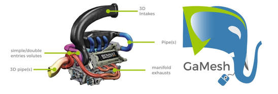 This software is called GaMesh, the remover of obstacles that makes meshing easier. It is now in the final step of its prototyping and shall be ready early 2018 for volutes, and will then be deployed on all the complex piping systems found in turbomachines. The estimated meshing time for a volute using this technique is lower than 15 minutes. 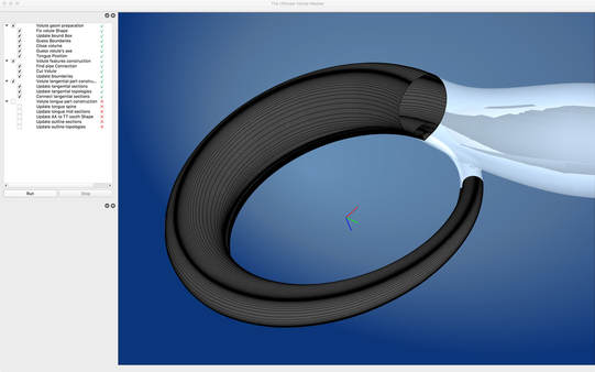 Using GaMesh along with the already existing structured meshing tools for blades, engineers will be able to optimize their geometries using reliable grids inducing limited bias in the simulation and providing faster convergence. For the team and the project, it will means a better use of the team force and time, and predicable results in lower time… One illustration of the power of structured meshes in the design process of a radial turbomachine is the comparison between such simulations with experimental results. The compressor behavior is for instance clearly well simulated for very different types of machines: 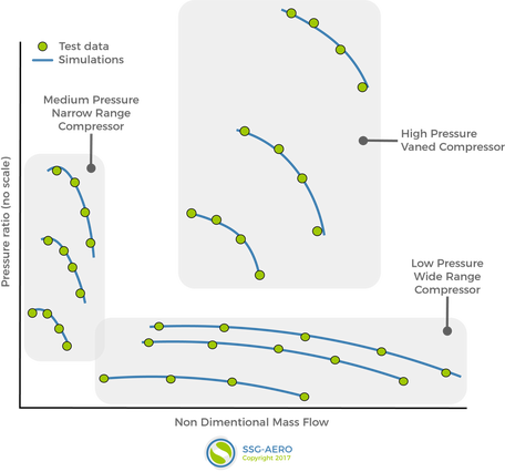 In the meantime many research institutes running complex unsteady analysis on complex machines insist on using such meshes as they request less memory and do offer faster convergence time.  One more thing…  Now that high quality meshing is possible, high quality meshing is not the weakest link of the design process anymore…
Engineers now have to be able to generate high quality geometries faster - by hand or using an optimizer - to reach the performance targets. For this challenge as well, SSG-AERO is developing another software: Shiva, a new environment that transforms your workflow and assists designers to create optimal geometries Shiva shall soon enable designers to produce amazingly smooth surfaces in no time and optimize them… A good contender… for a new entry in this young blog. SSG-AERO SSG-AERO is very proud to finally launch its blog which is intended to support our communication strategy on the internet. It is indeed oriented towards business.
Here you'll regularly find updates on
We shall regularly publish recipes on things we found using some of the great free / open source software we use, and share these tips in the spirit of Newe OCCT blog https://neweopencascade.wordpress.com Stay tuned! SSG-AERO |
|||||||||


 Flux RSS
Copyright © 2021 ssg-aero
|
|